High-Pressure High-Temperature Optical Floating Zone Furnace HKZ
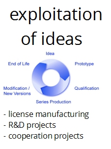
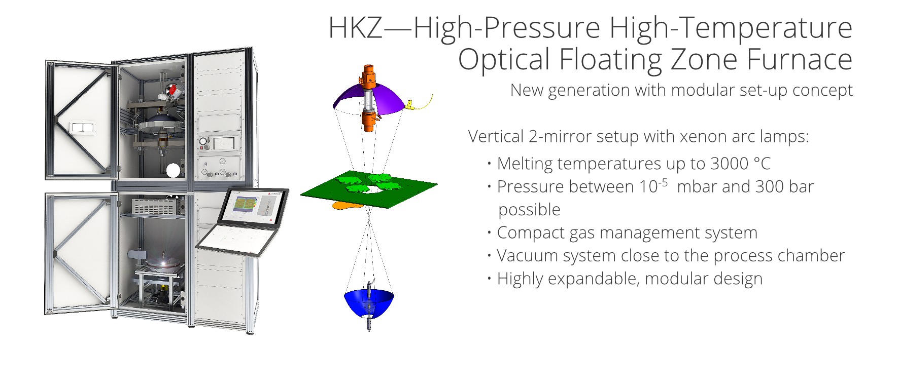
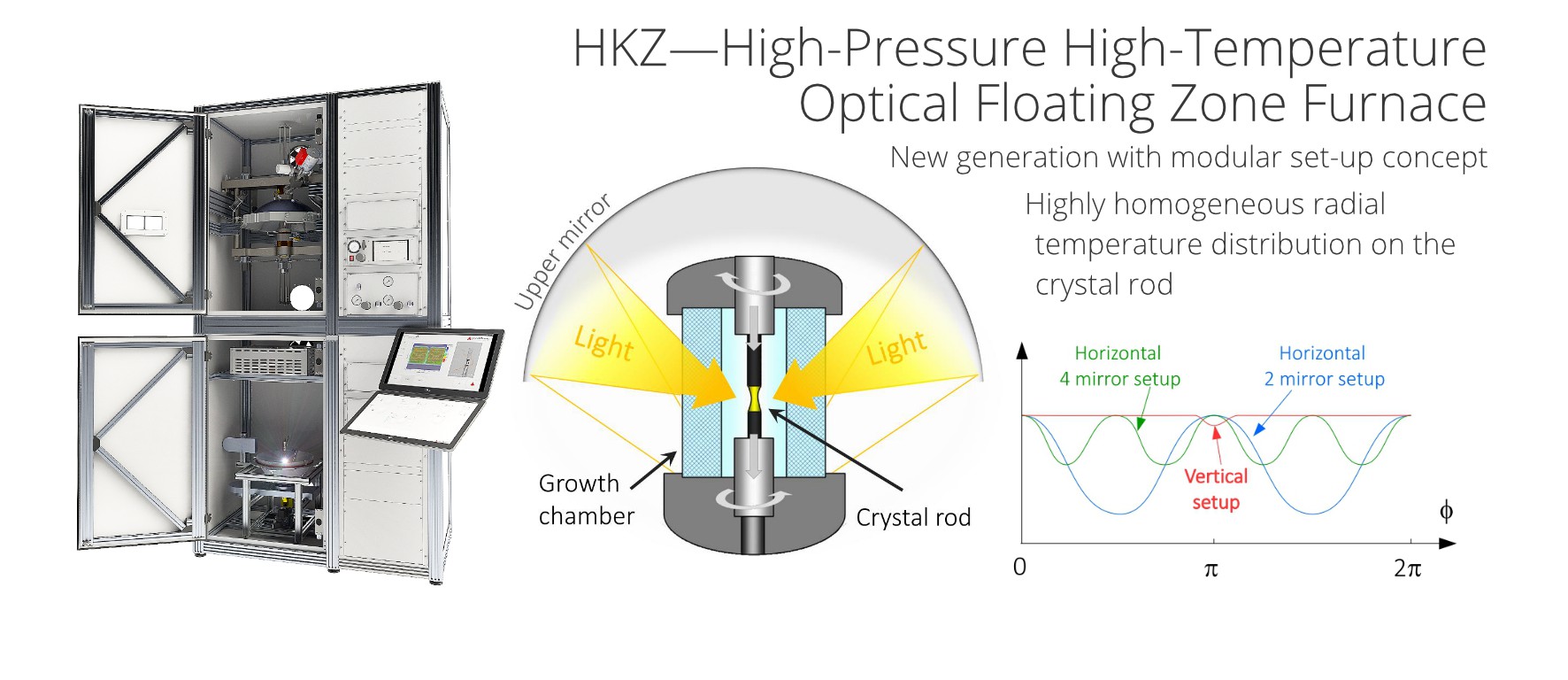
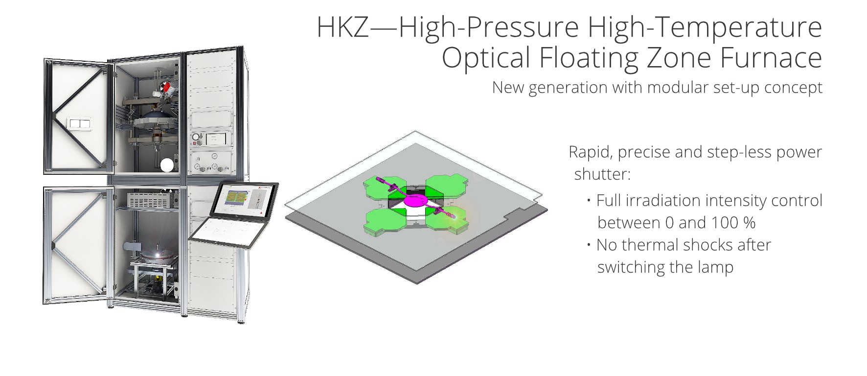
The abbreviation HKZ (Hochdruck-Kristallzüchtungsanlage) stands for a unique high-pressure optical floating zone crystal growth furnace. It features a vertical 2-mirror setup with a highly homogeneous and to a great extent controllable light power distribution on the crystal rod. One of the key characteristics of the furnace is the ability to work at pressures of up to 150 bar with different gases and mixtures in the growth chamber (currently we are working on a 300 bar version). Additionally, individual gas flow rates can be adjusted and controlled freely and independently over the complete pressure range.Using powerful xenon short arc lamps, melting temperatures over 3000 °C can be achieved. While the light power tuning range of arc lamps is limited, the thermal energy in the growth chamber is step-less adjustable between 0 and 100 % thanks to a power shutter system in the light beam.  Highly precise magnetically coupled linear and rotation feed through systems with pulling rates starting from 0.1 mm/h, advanced process monitoring technologies and a comfortable PLC user interface guarantee extensive control of the growth process. The temperature of feed rod, melt zone and crystal is measured directly via a patented in-situ temperature measurement system. An optional after-heater is applicable with all possible atmospheres and pressures—also with high-pressure oxygen atmospheres. This worldwide unique setup allows the user to rule the growth of materials, which are difficult or impossible to handle at low pressures due to the higher volatility or higher partial pressure of their elements. A very important characteristic is the highly developable and easily expandable, modular design of the HKZ furnace system, which allows add-ons and upgrades to all of current furnaces in an easy and cost-efficient way.
Key features

Practical advantages of the vertical double-ellipsoid optical scheme
. Influence of heat distribution and zone shape in the floating zone growth of selected oxide compounds. Journal of materials science, 45(8), 2223-2227.")
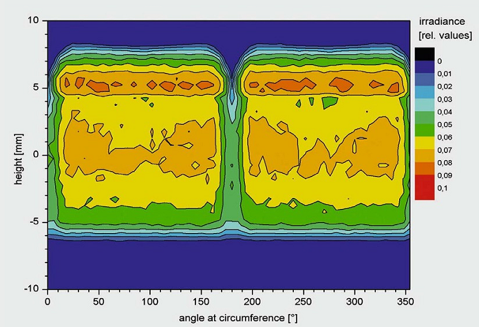
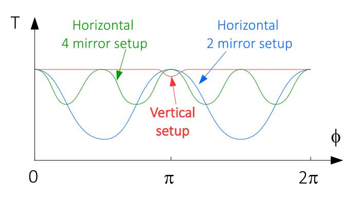 "In practice, a 3, 5 or 7 kW air-cooled xenon arc lamp positioned at the focal point of the lower mirror is used as the irradiation source. The molten zone is located inside the crystal growth chamber at the focus of the upper mirror. The FZ process proceeds by vertical pulling (downwards or upwards) of the feed rod and the growing crystal. The radiation power is controlled by both the lamp electrical power and a 4-sector mechanical flux shutter positioned between the mirrors. Here, on the basis of a huge number of FZ growth experiments with various materials, the fundamental practical advantages of the presented optical scheme are summarized for the first time as a background of theoretical investigations of light propagation within the present FZ setup in order to optimize parameters for specific crystal growth purposes. Axial symmetry of this optical configuration provides extreme uniform azimuthal heating of the melting zone. It permits to control the irradiation power range absorbed by the crystal surface from 0 to 100% by both mechanical flux shutter and electrical power of the arc lamp. Due to the large size of the upper mirror (600 mm) and the narrow bundle of rays illuminating the molten zone mainly from above, there is an easy access to the crystal growth chamber, even during the growth process, and sufficient space for mounting of auxiliary functional components in the neighbourhood of the growth chamber (e.g. afterheater for growing crystal, pyrometer, camera,) without any appreciable radiation absorption. Another feature of the vertical optical configuration is the narrow region of possible incident radiation angles onto the crystal <70° due to the cut-off by the mirror (instead of almost 140–180° for horizontal optical configurations). This enables much shorter quartz tubes for the growth chamber. The very high efficiency of the radiation flux focusing was confirmed for crystallization of refractory materials. In practice only one 5 kW (electrical power) xenon lamp is required for melting refractory oxides with 2800°C melting temperature. By contrast, four 3 kW xenon lamps (12 kW in total) are necessary for achieving similar temperatures in four-mirror horizontal optical furnaces. We connect this practical result with more effective focussing of the light flux emitted by the arc lamp and a narrower light profile on the crystal surface. For example, the width of the illuminated area can be as small as 1mm for the presented optical scheme, as will be shown further, in comparison to 5 mm for the horizontal optical scheme for a point source model."
Source: Souptel, D., Löser, W., & Behr, G. (2007). Vertical optical floating zone furnace: principles of irradiation profile formation. Journal of Crystal Growth, 300(2), 538-550.
(pdf file also on caltech.edu)
Technical details
Atmosphere
- Argon and oxygen (pure and in any mixture ratio)
- Many other gases possible on request
- Pressure: up to 300 bar (different version available: 10 bar, 50 bar, 150 bar, 300 bar)
- Turbulence suppression system
- PLC controlled gas flow: 0.25 l/min to 1 l/min, individually adjustable for different gases
- Vacuum: down to 1*10-5 mbar
- Turbo pump close to the process chamber, wide diameter connections
- UHV system possible on request
- Active titanium getter gas cleaning (removes O2 traces in argon down to 10-12 ppm, applicable under high-pressure conditions)
- Oxygen content measurement system
Growth chamber
- Highly transparent material
- Pressure-proved between 0 and 300 bar (or the max. pressure depending on the version)
- Long life span due to protective tube
- Sample holder for 6,8 mm or 9,8 mm samples
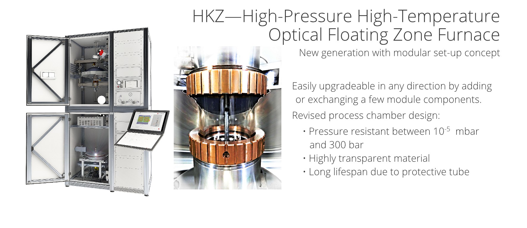
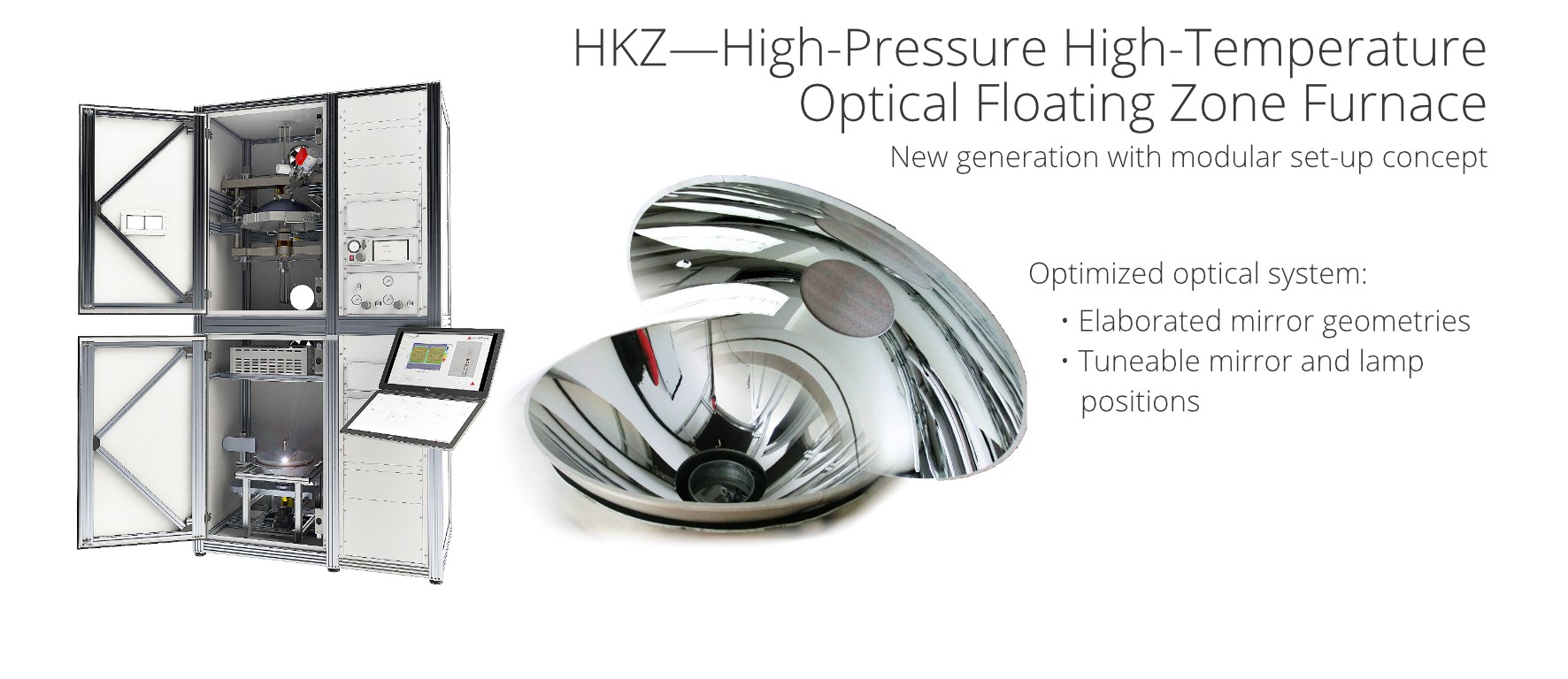
Optical heating
- Xenon short arc lamp, different kinds available between 3 kW and 15 kW
- Temperature: up to 3000 °C
- Lamp power control
- Power shutter in the light beam, step-less adjustable between 0 and 100 %
- Precise motor-driven lamp positioning unit, workable during the experiment
- Upper and lower optimized elliptical mirrors, aluminum or gold coated
- Mirror position adjustment system
Material rod moving
- Precise magnetically coupled linear and rotation feed through system
- Pulling rate: 0.1 mm/h to 200 mm/h (lower pulling rates possible on request)
- Fast service gear (approx. 0.6 mm/s )
- Pulling length: 195 mm
- Rotation rate: 0 to 70 rpm
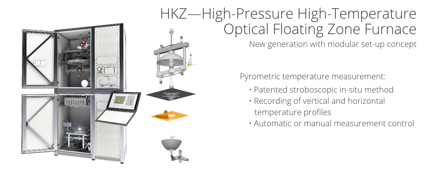
Temperature measurement
- Two-color pyrometer with a patented stroboscopic measurement method
- Adjustable time interval
- Adjustable position
- Several temperature ranges
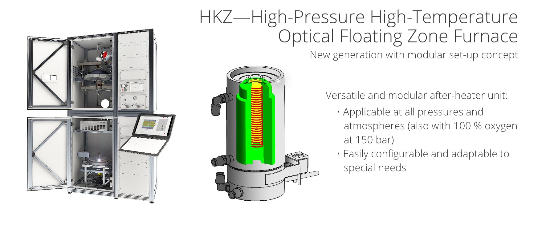
After-heater
- Versatile and modular unit
- Applicable with all possible atmospheres and pressures
- Easily exchangeable heater coils
- Highly adaptable to special needs
Process control and monitoring
- High-resolution CCD camera with specialized lenses and filters
- Monitoring application: visual control, video recordings, snapshots and length measurements during the growth process
- Power ramp and traveling ramp functions
- Front window for direct observation of the growth chamber
- All system parameters are comfortably controllable and adjustable via a PLC-based software application with two 27" touch screens
- Safety system with protection housing, door lock system, automatic shut down function
Required laboratory connections
- Gas supply with the intended pressure
- Exhaust air system
- Energy supply: 3-phase AC, 50 Hz, 400 V, 63 A
- Cooling water
Furnace dimensions
- Height: 3020 mm , width: 1631 mm, depth: 920 mm
References
The following users of a HKZ have agreed to provide their contact data for exchange of experiences:
 Dr. Hugo Schlich, MaTecK GmbH
- Dr. A. C. Komarek, Prof. Dr. Liu Hao Tjeng, MPI CPfS Dresden
 Dr. Jiaqiang Yan, Dr. Brian Sales, Oak Ridge National Laboratory
- Dr. Jennifer Zheng, Dr. John F. Mitchell, Argonne National Laboratory
 Dr. Qisi Wang, Prof. Dr. Jun Zhao, Fudan University Shanghai
Publications: materials grown with the HKZ furnace system
- Feng, H., Huang, S., Yu, H., Zheng, J., Liu, C., Yang, X., Yang, F. (2022). Concentration and temperature dependence behaviors of photoluminescence and scintillation properties of Lu2O3:Pr single crystals. Journal of Alloys and Compounds, 903, 163884.
- Guo, H., Zhao, L., Baenitz, M., Fabrèges, X., Gukasov, A., Melendez Sans, A., Khomskii, D., Tjeng, L. H., Komarek, A. C. (2021). Emergent 1/3 magnetization plateaus in pyroxene CoGeO3. Physical Review B, 3, L032037.
- Zhang, P., Gao, M., Guo, R., Xu, J., Wang, Y., Luo, L. (2021). Structural and optical properties of GdAlO3:Tb3+ crystal obtained by optical floating zone method. Optik, 239, 166880.
- Zhao, L., Hu, Z., Guo, H., Geibel, C., Lin, H.-J., Chen, C.-T., Khomskii, D., Tjeng, L. H., Komarek, A. C. (2021). Single Crystal Growth and Physical Properties of Pyroxene CoGeO3. Crystals, 11(4), 378.
- Haihang, Y., Qianli, L., Changjiang, L., Wei, J., Xuechun, Y., Mei, Y., Rihua, M., He, F. (2021). Comparison of Photoluminescence and Scintillation Properties Between Lu2O3:Eu Single Crystal and Transparent Ceramic. IEEE Transactions on Nuclear Science, 68, 4.
- Gao, M., Zhang, P., Luo, L., Guo, R., Wang, Y. (2021). Structural and optical characterization of Gd2SiO5:Tb3+ crystal obtained by optical floating zone method. Optik, 225, 165814.
- Tay, D., Shang, T., Puphal, P., Pomjakushina, E., Ott, H.-R., Shiroka, T. (2020). Unusual 27Al NMR shift in the Weyl-fermion systems LaAlGe and PrAlGe. Physical Review B, 102, 241109.
- Upton, M. H., Zhang, J., Zheng, H., Said, A., Mitchell, J. F. (2020). Electronic coupling in square planar La4Ni3O8. Journal of Physics: Condensed Matter, 32, 42.
- Guo, H., Li, Z. W., Chang, C. F., Hu, Z., Kuo, C.-Y., Perring, T. G., Schmidt, W., Piovano, A., Schmalzl, K., Walker, H. C., Lin, H. J., Chen, C. T., Blanco-Canosa, S., Schlappe, J., Schüßler-Langeheine, C., Hansmann, P., Khomskii, D. I., Tjeng, L. H., Komarek, A. C. (2020). Charge disproportionation and nano phase separation in RSrNiO4. Scientific Reports, 10, 18012.
- Zhang, J., Zheng, H., Chen, Y.-S., Ren, Y., Yonemura, M., Huq, A., Mitchell, J. F. (2020). High oxygen pressure floating zone growth and crystal structure of the metallic nickelates R4Ni3O10 (R=La, Pr). Physical Review Materials, 4, 083402.
- Zheng, H., Wang, B.-X., Phelan, D., Zhang, J., Ren, Y., Krogstad, M. J., Rosenkranz, S., Osborn, R., Mitchell, J. F. (2020). Oxygen Inhomogeneity and Reversibility in Single Crystal LaNiO3−δ. Crystals 10(7), 557.
- Dey, K., Sauerland, S., Werner, J., Skourski, Y., Abdel-Hafiez, M., Bag, R., Singh, S., Klingeler, R. (2020). Magnetic phase diagram and magnetoelastic coupling of NiTiO3. Physical Review B, 101, 195122.
- Zhang, J., Phelan, D. Botana, A. S., Chen, Y.-S., Zheng, H., Krogstad, M., Wang, S. G., Qiu, Y., Rodriguez-Rivera, J. A., Osborn, R., Rosenkranz, S., Norman, M. R., Mitchell, J. F. (2020). Intertwined density waves in a metallic nickelate. Nature Communications, 11, 6003.
- Huangfu, S., Jakub, G. D., Zhang, X., Blacque, O., Puphal, P., Pomjakushina, E., von Rohr, E. O., Schilling, A. (2020). Anisotropic character of the metal-to-metal transition in Pr4Ni3O10. Physical Review B, 101, 104104.
- Haihang, Y., Changjiang, L., Zhikun, Z., Shimin, H., Yunling, Y., Rihua, M., He, F., Jingtai, Z. (2020). Single crystal growth and luminescent properties of YSH:Eu scintillator by optical floating zone method. Chemical Physics Letters, 738, 136916.
- Pejchal, J., Guguschev, C., Schulze, M., Jary, V., Mihokova, E., Rubesova, K., Jakes, V., Barta, J., Nikl, M. (2019). Luminescence and scintillation properties of strontium hafnate and strontium zirconate single crystals. Optical Materials, 98, 109494.
- Liu, F., Xu, C., Shen, S., Li, N., Guo, H., Lü, X., Xiang, H., Bellaiche, L., Zhao, J., Yin, L., Yang, W., Wang, W., Shen, J. (2019). Pressure-induced large enhancement of Néel temperature and electric polarization in the hexagonal multiferroic Lu0.5Sc0.5FeO3. Phys. Rev. B, 100, 214408.
- Dey, K., Hergett, W., Telang, P., Abdel-Hafiez, M. M., Klingeler, R. (2019). Magnetic properties of high-pressure optical floating-zone grown LaNiO3 single crystals. Journal of Crystal Growth, 524, 125157.
- Zheng, H., Zhang, J., Wang, B., Phelan, D., Krogstad, M. J., Ren, Y., Phelan, W. A., Chmaissem, O., Poudel, B., Mitchell, J. F. (2019). High pO2 Floating Zone Crystal Growth of the Perovskite Nickelate PrNiO3. Crystals, 9(7), 324.
- Hergett, W., Neef, C., Wadepohl, H., Meyer, H.-P., Abdel-Hafiez, M. M., Ritter, C., Thauer, E., Klingeler, R. (2019). High-pressure optical floating-zone growth of Li2FeSiO4 single crystals. Journal of Crystal Growth, 515, 37-43.
- Hergett, W., Jonak, M., Werner, J., Billert, F., Sauerland, S., Koo, C., Neef, C., Klingeler, R. (2019). Synthesis and magnetism of a Li2FeSiO4 single crystal. Journal of Magnetism and Magnetic Materials, 477, 1-3.
- Zhuang, L., Feng, H., Huang, S., Zhang, Z., Yong, W., Mao, R., Zhao, J. (2019). The luminescent properties comparison of RE2O3:Eu (RE = Lu, Y, Sc) with high and low Eu doping concentrations. Journal of Alloys and Compounds, 781 302-307.
- Puphal, P., Mielke, C., Kumar, N., Soh, Y., Shang, T., Medarde, M., White, J. S., Pomjakushina, E. (2019). Bulk single-crystal growth of the theoretically predicted magnetic Weyl semimetals RAlGe (R = Pr, Ce). Physical Review Materials, 3, 024204.
- Phelan, W. A., Zahn, J., Kennedy, Z., McQueen, T. M. (2019). Pushing boundaries: High pressure, supercritical optical floating zone materials discovery. Journal of Solid State Chemistry, 270, 705-709.
- Ryu, G., Guo, H., Zhao, L., Fernández‐Díaz, M. T., Drees, Y., Li, Z. W., Hu, Z., Komarek, A. C. (2018). Single Crystal Growth and Magnetic Properties of High Oxidation State Material Ba2CoO4. Physica Status Solidi RRL - Rapid Research Letters 13, 1800537.
- Wan, H., Wang, Y., Zhuang, L., Huang, S., Zhang, Z., Xu, Z., Mao, R., Feng, H., Zhao, J. (2018). Photoluminescence, scintillation properties and trap states of La2Si2O7Ce single crystal. Materials Research Express, 5, 8.
- Wang, B.-X., Rosenkranz, S., Rui, X., Zhang, J., Ye, F., Zheng, H., Klie, R. F., Mitchell, J. F., Phelan, D. (2018). Antiferromagnetic defect structure in LaNiO3−δ single crystals. Physical Review Materials, 2, 064404.
- Zheng, H., Zhang, J., Stoumpos, C. C., Ren, Y., Chen, Y.-S., Dally, R., Wilson, S. D., Islam, Z., Mitchell, J. F. (2018). Controlled vapor crystal growth of Na4Ir3O8: A three-dimensional quantum spin liquid candidate. Physical Review Materials, 2, 043403.
- Guo, H., Li, Z. W., Zhao, L., Hu, Z., Chang, C. F., Kuo, C.-Y., Schmidt, W., Piovano, A., Pi, T. W., Sobolev, O., Khomskii, D. I., Tjeng, L. H. & Komarek, A. C. (2018). Antiferromagnetic correlations in the metallic strongly correlated transition metal oxide LaNiO3. Nature Communications, 9:43.
- Li, Z. W., Guo, H., Hu, Z., Chan, T. S., Nemkovski, K., & Komarek, A. C. (2017). Single-crystal growth and physical properties of 50% electron-doped rhodate Sr1.5La0.5RhO4 Physical Review Materials, 1(4), 044005.
- Schreiber, N. J., Zhang, J., Zheng, H., Freeland, J. W., Chen, Y. S., Mitchell, J. F., & Phelan, D. (2017). Single crystal growth and structural evolution across the 1st order valence transition in (Pr1− yYy)1− xCaxCoO3-δ. Journal of Solid State Chemistry, 254, 69-74.
- Zhang, J., Botana, A. S., Freeland, J. W., Phelan, D., Zheng, H., Pardo, V., ... & Mitchell, J. F. (2017). Large orbital polarization in a metallic square-planar nickelate. Nature Physics, 13, 864–869.
- Neef, C., Wadepohl, H., Meyer, H. P., & Klingeler, R. (2017). High-pressure optical floating-zone growth of Li(Mn,Fe)PO4 single crystals. Journal of Crystal Growth, 462, 50-59.
- Shen, Y., Li, Y. D., Wo, H., Li, Y., Shen, S., Pan, B., Wang Q., Walker H. C., Steffens P., Boehm M., Hao Y., Quintero-Castro D. L., Harriger L. W., Frontzek M. D., Hao L., Meng S., Zhang Q., Chen G., Zhao J. (2016). Evidence for a spinon Fermi surface in a triangular-lattice quantum-spin-liquid candidate. Nature, 540, 559–562.
- Zhang, J., Chen, Y. S., Phelan, D., Zheng, H., Norman, M. R., & Mitchell, J. F. (2016). Stacked charge stripes in quasi-2D trilayer nickelate La4Ni3O8. PNAS, 113 (32) 8945-8950.
- Guo, H., Hu, Z., Pi, T. W., Tjeng, L. H., & Komarek, A. C. (2016). Single Crystal Growth of Pure Co3+ Oxidation State Material LaSrCoO4. Crystals, 6(8), 98.
- Li, Z. W., Liu, C. F., Skoulatos, M., Tjeng, L. H., & Komarek, A. C. (2015). Floating zone growth of Ba-substituted ruthenate Sr2−xBaxRuO4. Journal of Crystal Growth, 427, 94-98.
- Cao, H. B., Zhao, Z. Y., Lee, M., Choi, E. S., McGuire, M. A., Sales, B. C., Zhou, H. D., Yan, J.-Q., and Mandrus, D. G. (2015). High pressure floating zone growth and structural properties of ferrimagnetic quantum paraelectric BaFe12O19. APL Materials, 3, 062512.
-
Steil, D., Schmitt, O., Fetzer, R., Kubota, T., Naganuma, H., Oogane, M., Ando, Y., Rodan, S., Blum, C. , Balke, B., Wurmehl, S., Aeschlimann, M., and Cinchetti, M. (2015). Impact of local order and stoichiometry on the ultrafast magnetization dynamics of Heusler compounds. Journal of Physics D: Applied Physics, 48(16), 164016.
-
Zhang, J., Zheng, H., Malliakas, C. D., Allred, J. M., Ren, Y., Li, Q. A., Han, T.-H. & Mitchell, J. F. (2014). Brownmillerite Ca2Co2O5: Synthesis, Stability, and Re-entrant Single Crystal to Single Crystal Structural Transitions. Chemistry of Materials, 26(24), 7172-7182.
- Bauer, A., Regnat, A., Blum, C. G., Gottlieb-Schönmeyer, S., Pedersen, B., Meven, M., Wurmehl, S, Kuneš, J & Pfleiderer, C. (2014). Low-temperature properties of single-crystal CrB2. Physical Review B, 90(6), 064414. (Also on archiv.org.)
- Omar, A., Blum, C. G., Löser, W., Büchner, B., & Wurmehl, S. (2014). Effect of annealing on spinodally decomposed Co2CrAl grown via floating zone technique. Journal of Crystal Growth, 401, 617-621. (Also on arxiv.org.)
- Brasse, M., Chioncel, L., Kuneš, J., Bauer, A., Regnat, A., Blum, C. G. F., Wurmehl, S., Pfleiderer, C., Wilde, M. A. & Grundler, D. (2013). de Haas–van Alphen effect and Fermi surface properties of single-crystal CrB2. Physical Review B, 88(15), 155138. (Also on arxiv.org.)
- Omar, A., Dimitrakopoulou, M., Blum, C. G. F., Wendrock, H., Rodan, S., Hampel, S., Löser, W., Büchner, B., & Wurmehl, S. (2013). Phase Dynamics and Growth of Co2Cr1–xFexAl Heusler Compounds: A Key to Understand Their Anomalous Physical Properties. Crystal Growth & Design, 13(9), 3925-3934.
-
Blum, C. G., Ouardi, S., Fecher, G. H., Balke, B., Kozina, X., Stryganyuk, G., Ueda, S., Kobayashi, K., Felser, C., Wurmehl, S., & Büchner, B. (2011). Exploring the details of the martensite–austenite phase transition of the shape memory Heusler compound Mn2NiGa by hard x-ray photoelectron spectroscopy, magnetic and transport measurements. Applied Physics Letters, 98(25), 252501.
- Wizent, N., Behr, G., Löser, W., Büchner, B., & Klingeler, R. (2011). Challenges in the crystal growth of Li2CuO2 and LiMnPO4. Journal of Crystal Growth, 318(1), 995-999.
- Cao, C., Löser, W., Behr, G., Klingeler, R., Leps, N., Vinzelberg, H., & Büchner, B. (2011). Self-flux growth of large EuCu2Si2 single crystals. Journal of Crystal Growth, 318(1), 1043-1047.
-
Behr, G., Löser, W., Wizent, N., Ribeiro, P., Apostu, M. O., & Souptel, D. (2010). Influence of heat distribution and zone shape in the floating zone growth of selected oxide compounds. Journal of materials science, 45(8), 2223-2227.
- Blum, C. G. F., Jenkins, C. A., Barth, J., Felser, C., Wurmehl, S., Friemel, G., Hess, C, Behr, G, Büchner, B, Reller, A, S. Riegg, S., Ebbinghaus, S. G., Ellis, T., Jacobs, P. J., Kohlhepp, J. T. & Swagten, H. J. M. (2009). Highly ordered, half-metallic Co2FeSi single crystals. Applied Physics Letters, 95(16), 161903.
- Wizent, N., Behr, G., Lipps, F., Hellmann, I., Klingeler, R., Kataev, V., Löser, W., Sato, N. & Büchner, B. (2009). Single-crystal growth of LiMnPO4 by the floating-zone method. Journal of Crystal Growth, 311(5), 1273-1277. (Also on uni-heidelberg.de.)
- Behr, G., Löser, W., Souptel, D., Fuchs, G., Mazilu, I., Cao, C., Köhler, A., Schultz, L. & Büchner, B. (2008). Crystal growth of rare earth-transition metal borocarbides and silicides. Journal of Crystal Growth, 310(7), 2268-2276.
Publications: methodical considerations concerning the HKZ system
- Phelan, W. A., Zahn, J., Kennedy, Z., McQueen, T. M. (2019). Pushing boundaries: High pressure, supercritical optical floating zone materials discovery. Journal of Solid State Chemistry, 270, 705-709.
- Wizent, N., Behr, G., Löser, W., Büchner, B., & Klingeler, R. (2011). Challenges in the crystal growth of Li2CuO2 and LiMnPO4. Journal of Crystal Growth, 318(1), 995-999.
- Behr, G., Löser, W., Wizent, N., Ribeiro, P., Apostu, M. O., & Souptel, D. (2010). Influence of heat distribution and zone shape in the floating zone growth of selected oxide compounds. Journal of materials science, 45(8), 2223-2227.
- Behr, G., Löser, W., Souptel, D., Fuchs, G., Mazilu, I., Cao, C., Köhler, A., Schultz, L. & Büchner, B. (2008). Crystal growth of rare earth-transition metal borocarbides and silicides. Journal of Crystal Growth, 310(7), 2268-2276.
- Palme, M., Riehemann, S., Horst, A., Souptel, D., Behr, G. (2004). Optical simulation of a radiation heating / Optische Simulation einer Strahlungsheizung. Fraunhofer IOF Annual Report 2004, 70-71.

Fig: First HKZ generation, working facility of MaTecK GmbH, Location ScIDre GmbH Dresden